Types Of Flywheel
BRACT, Vishwakarma Institute of Technology, Pune

TY. B. tech
Mechanical Engineering Department
DOM - Home Assignment - TYMEA, Batch 2, Group 5
Guided by - Prof. Rajkumar Bhagat
Group Members/Authors -
Nivedita Bhagwat - RN 31
Pranjali Bhople - RN 38
Vedant Bhosale - RN 41
Harsh Bhutada - RN 44
Chhavi Kumari - RN 52
What is a flywheel?
A flywheel used in machines serves as a reservoir, which stores energy during the period when the supply of energy is more than the requirement, and releases it during the period when the requirement of energy is more than the supply. In the case of steam engines, internal combustion engines, reciprocating compressors and pumps, the energy is developed during one stroke and the engine is to run for the whole cycle on the energy produced during this one stroke.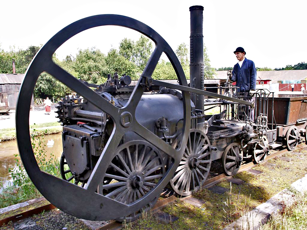
For example, in internal combustion engines, the energy is developed only during expansion or power stroke which is much more than the engine load and no energy is being developed during suction, compression and exhaust strokes in case of four stroke engines and during compression in case of two stroke engines. The excess energy developed during power stroke is absorbed by the flywheel and releases it to the crankshaft during other strokes in which no energy is developed, thus rotating the crankshaft at a uniform speed. A little consideration will show that when the flywheel absorbs energy, its speed increases and when it releases energy, the speed decreases.
Hence a flywheel does not maintain a constant speed, it simply reduces the fluctuation of speed. In other words, a flywheel controls the speed variations caused by the fluctuation of the engine turning moment during each cycle of operation. In machines where the operation is intermittent like *punching machines, shearing machines, riveting machines, crushers, etc., the flywheel stores energy from the power source during the greater portion of the operating cycle and gives it up during a small period of the cycle. Thus, the energy from the power source to the machines is supplied practically at a constant rate throughout the operation.
History
Principle of flywheel is found in the Neolithic spindle and the potter’s wheel and also circular sharpening stones in antiquity. In early 11th century, Ibn Bassal developed and found the use of flywheel.The use of the flywheel is for mechanical device to equalize the speed of rotation and stop the fluctuations.In the Industrial revolution, James Watt has contributed to the development of flywheel in the steam engine and his belonging James Pickard used the flywheel combined to a crank so that to transform reciprocating motion into rotary motion.
The energy equation depends on the angular velocity and moment of inertia of the flywheel.
How does Flywheel Works?
The basic working principle of a flywheel is that it absorbs rotational energy during the power stroke and delivers that energy during other strokes ( suction, compression, and exhaust).The energy equation depends on the angular velocity and moment of inertia of the flywheel.

Thus, it is obvious that the energy stored in a flywheel will increase with the increase in weight, size, and angular velocity.
Working method:
- The electric motor gives power to the flywheel at the very initial stage.
- This movement causes the piston to move and burn fuel inside the combustion chamber.
- Once the power stroke is activated the flywheel draws power from the power stroke and uses it for the other three strokes.
- In this way, It helps in stabilizing the rotational movement of the transmission system

Types of Flywheel
1. Solid Disc Flywheel
A solid disc flywheel is a kind of Flywheel. It is used in single flywheel threshers, which are made of cast iron. Solid Disc Flywheel The Flywheel is equipped with a hub and disc. In the design calculations of a solid disc flywheel, various parameters are used as inputs. This includes the dimensions of the Solid Disc Flywheel. In addition, the resulting functional values are calculated.2. Rimmed Flywheel
A rim-type wheel will detonate at a much lower rotary speed than a solid disc-type wheel of the same weight & diameter. For minimal weight and high energy-storage capacity, flywheels can be made from high-strength steel and produced as a tapered disc, which is thicker in the center.3. High-Velocity Flywheel
In this type of Flywheel, the high-velocity Flywheel has a velocity between 30000 rpm to 80000 rpm. It can also be adjusted up to 100,000 rpm. They have magnetic levitation bearings & require little maintenance. In terms of size/capacity, they are lighter in weight than low-velocity flywheels. They are more expensive than low-velocity flywheels.4. Low-Velocity Flywheel
In this type of Flywheel, the low-velocity Flywheel has a velocity of 10000 rpm. They are heavier and heavier than the high-velocity Flywheel. They require periodic maintenance and do not use magnetic levitation bearings.Their installation requires special concrete construction to bear its own weight. They are more economical than high-velocity flywheels.
Functions of flywheel
- A flywheel promotes the smooth running of the vehicle.
- It stores energy during the power stroke and releases it during other strokes.
- It also helps in charging the battery.
- Balances the crankshaft.
- It is very important for starting the engine from the rest condition.
Applications of Flywheels
- In wind turbines
- Along with motor driven generator to store energy
- In automobile engines
- In electric cars to boost speed (in experimental stage)
- In advanced locomotive propulsion systems
- In advanced technology transit buses
- In satellites to control direction
- In Big electricity grids for protection against interruptions
Flywheel Construction or Parts:
The flywheels are generally made by the casting process. This helps in maintaining the rigidity of the device. The structure of an armed flywheel is given below.
Rim:
- The outer circular disc of the flywheel is called the rim. The rim is made heavier than the inner body this is to provide a better kinetic energy transfer.
- The rim also has teeth on the outer surface with meshes with the electric motor and helps in the starting of the engine.
- Once the engine is running it also generates electricity by rotating the motor and making it a generator.
Web or arms:
- Web or arms are the supporting structure. It supports the rim against the vibrations caused due to the rotation.
- The deciding factor of whether the flywheel should be an arm type or a web type depends on the size of the flywheel.
If the diameter is less than 600mm it is a web type and cast in one piece, if the diameter is greater than 600mm and less than 2.5m then it is arm type and cast in one piece and if the diameter is greater than 2.5m then it should be an arm type but here rim and body are cast separately.
Bore:
The bore of the flywheel is a hole made with a key way to fit the driving shaft in it.
Structure of a Modern Flywheel:
Cover
Springs
Planetary wheel
Axial and radial bearings
Support disc and
Sliding shoe

Flywheel cover:
The cover is a structural casing of the flywheel; it is rigid and solid. It also rotates and protects it against external barriers
Springs:
The spring used here acts as a damper for sudden vibrations. Hence, they protect from sudden jerks.
Planetary wheel:
A planetary wheel is situated with a planetary gear. When this gear is rotated and it provides a compound moment of other internal gears.
Axial and radial bearings:
Whenever there is an imbalance in the radial forces, these are compensated by these bearings.
Support disc:
A support disc is situated inside to support the springs and other moving parts.
Sliding shoe:
This is situated on the inner wall of the flywheel and is used to reduce the wear caused.
Materials used for making Flywheel:
The materials used for making a flywheel are:
Cast Iron: Traditional flywheels are made of cast irons. The major advantage of cast iron is that it is cheap. There is minimum or no need for machining as it can directly be used after casting operation. They also act as great dampers and absorb vibrations. They also have few disadvantages such as, they have sudden failure and they also offer poor tensile strength.
Steel: Nowadays flywheels are made of high-strength steel as they offer better tensile strength and are corrosion resistant. They are also very durable and do not undergo failure very easily. Steels are considered to be a better option when compared to cast iron.
GFRP: GFRP stands for graphite fiber-reinforced polymer. This is considered to be the best choice for making flywheels for modern-day cars and automobiles. They offer a great density and tensile strength and are perfect for making flywheels.
Material of the flywheel depends upon the application like cast iron, grey cast iron, mild steel etc. Flywheels are manufactured by a casting process with single materials with high strength but more weight. In order to get high strength and reduce weight, we go for composite materials for flywheel.
Designing of flywheel and one example:
Step-1: Coefficient of fluctuation calculation
Input required: Maximum & minimum speed
Flywheel inertia/size depends upon the fluctuations in speed. The difference between maximum & minimum speeds during a cycle is called maximum fluctuation of speed.
The ratio between maximum fluctuations of speed to mean speed is called coefficient of fluctuation of speed (Cs).
Consider, Ѡ max =Max. Speed during the cycle
Ѡmin = Min. speed during the cycle
Ѡmean =Mean speed = (Ѡ max + Ѡ min) /2…….eq.1
Therefore, Coefficient of Fluctuation of speed,
Cs = [2*(Ѡmax–Ѡmin)]/[Ѡmax+Ѡmin]…….eq.2
Note: The smaller the Cs value, larger the flywheel, but smoother the operation.
Step-2: Mass moment of inertia calculation
Input required: kinetic energy of the system
The general equation of kinetic energy for a flywheel system is given as,
Ke = 0.5* I* (Ѡmax2 – Ѡmin2) ………..eq.3
Rewriting eq.3, we get
Ke = 0.5 I (Ѡmax + Ѡmin) (Ѡmax – Ѡmin)…………eq.4
Substituting eq.1 & 2 in eq.4, we get
I = Ke / Cs Ѡmean2……………..eq.5
eq.5 is used to obtain necessary flywheel inertia corresponding to variations in speed.
We will try out a simplified problem on flywheel sizing and calculate the required moment of inertia.
Regarding units ( Important ):
Ke – N.m
Ѡ – rad/sec
I – Kg.m2
Example:
Let us consider a punching machine driven by a 3KW, 1000RPM powered motor with a gear set of 5:1 and a stroke length of 250mm. Rated capacity of the punching machine is 22KN.
Consider coeff. of fluctuation of speed, Cs = 0.02 (Value to be considered by the designer)
Since it is a small machine, diameter of the flywheel should be as small as possible.
Consider 500mm to be the max size of the flywheel dia.
Calculate the mass moment of inertia required for the flywheel of the punching press machine.
Solution:
Step-1: Coefficient of fluctuation (Cs) calculation
The value is given as,
Cs=0.02
Step-2: Mass moment of inertia (I) calculation
Input required: kinetic energy of the system- to be calculated
Kinetic energy of the system (Ke) calculation:
Work done, W = 22*10^3*0.25*0.15 (Assume rated load delivered during 15% of power stroke)
Therefore, W = 825Nm
Thus, Energy absorbed is 825Nm.
Now, let us calculate the mean torque acting on the shaft, Tmean = 3*10^3 / 2*π*(1000/60)
Therefore, Tmean = 28.66Nm
Work done per cycle is (Energy supplied), Wc= 2π*28.66*5 = 900 Nm
Therefore, Kinetic energy of the system is,
Ke=W–Wc*0.08 (Energy absorbed – Energy supplied* factor for loss)
Ke = 825 – 900 *0.08 (0.08 – factor for losses. Again dependent on the designer)
Ke = 753Nm
Therefore, mass moment of inertia as per eq.5 is
I = 753 / 0.02 (2π*1000/60)2
I = 3.43 Kg.m2
Hence, the flywheel sizing/design calculation for the above example shows that the required mass moment of inertia for this application should be = 3.43 Kg.m2.
Conclusion
Flywheels
are one of the most promising technologies for replacing conventional
lead acid batteries as energy storage systems for a variety of
applications, including automobiles, economical rural electrification
systems, and stand-alone, remote power units commonly used in the
telecommunications industry.
Recent advances in the mechanical properties of composites has rekindled interest in using the inertia of a spinning wheel to store energy.
Informative
ReplyDeleteGood work
Information is good
ReplyDeleteUseful post !!
ReplyDeleteVery well explained.
ReplyDeleteinsightful
ReplyDeleteExcellent work💯👍
ReplyDelete